What Goes Into an ILA Hut BUILD
A Complete Design & Build-Out Breakdown
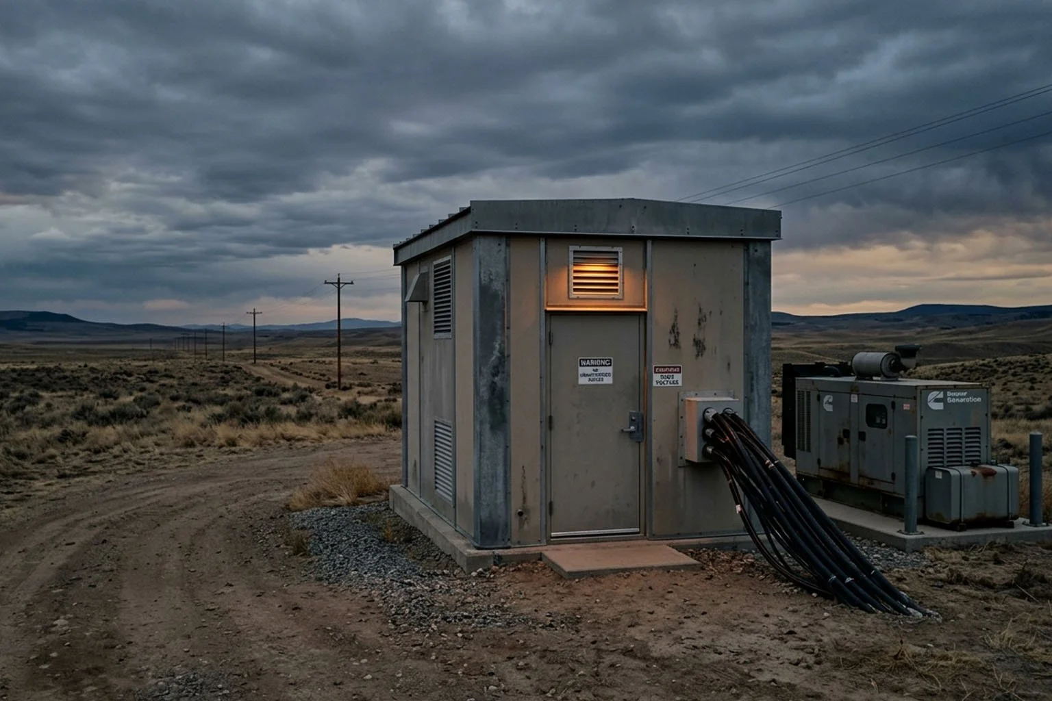
ILA (Integrated Line Amplifier) huts are the unsung backbone of long-haul fiber networks. Every 60–100 km along a terrestrial or submarine cable route, one of these hardened, unmanned facilities keeps the signal alive, amplifying light across thousands of miles of fiber without missing a beat. When a data center is decommissioned and routes need to be rerouted, these huts are what keep the backbone running.
So what actually goes into building one? Here's the complete picture.
The Structure
A standard ILA hut is a prefabricated steel or concrete shelter, typically 160–320 sq ft, housing 2–6 equipment bays. That footprint is small, but everything inside it has to perform reliably for years, in any climate, without regular human presence.
Structural design priorities include weatherproofing and environmental hardening against moisture, dust, and pests rated for local wind and seismic loads; reinforced security with tamper alarms and remote monitoring cameras; a poured concrete foundation (often elevated for flood mitigation and cable entry management); hardened conduit runs with pressurized cable vaults for sheath breach detection; and a vestibule or air lock in harsh climates to prevent thermal shock to equipment.
Every design choice traces back to the same requirement: this building has to work without anyone in it.
Power
Power reliability isn't optional at a remote unmanned site. ILA hut power architecture layers redundancy at every level.
Utility & Transfer Dual utility feeds from separate paths feed into an Automatic Transfer Switch (ATS). If one fails, the other takes over — automatically.
Standby Generator Sized at N+1 above the calculated critical load, typically 30–100 kW. Fuel autonomy runs 72–96 hours minimum, with 7-day autonomy specified for the most remote sites. Cold-climate installations add coolant and block heaters for reliable cold-starts. Generator status, fuel level, run hours, and fault states are all reported to the NOC via SNMP.
–48V DC Plant The industry-standard –48V DC plant — sourced from vendors like Emerson/Vertiv or Alpha Technologies — provides 200–600A of capacity with N+1 rectifier modules. Battery backup (VRLA or lithium-ion) delivers 4–8 hours at full load. A Low Voltage Disconnect (LVD) protects battery strings from deep discharge.
DC Distribution A main DC fuse or breaker panel distributes –48V to individual equipment loads, with GMT fuses or circuit breakers per bay. Every circuit is documented and labeled.
Cooling
Optical amplifiers and electronics are sensitive to temperature swings. A stable environment extends equipment life and prevents unexpected failures.
ILA huts use DX (direct expansion) precision air conditioning, wall or ceiling mounted, in an N+1 configuration. Two units, each capable of handling the full cooling load, with automatic failover. Target environment: 65–75°F, 40–55% relative humidity.
An environmental controller rotates the lead and standby units to equalize runtime hours. Temperature and humidity sensors at inlet, outlet, and ambient positions feed high-temp alarms that trigger before equipment reaches its thermal shutdown threshold.
Hot aisle/cold aisle principles apply even in a 200 sq ft space. Blanking panels fill every unused rack unit. Overhead cable tray supports front-to-back rack airflow.
Optical Equipment
The whole purpose of the hut is amplification. The rack layout reflects that.
Optical Line Amplification EDFA (Erbium-Doped Fiber Amplifier) shelves form the core, one shelf per fiber pair direction (east and west), with multiple amplifier modules per shelf. Dispersion Compensation Modules (DCMs) are installed in-line as passive 1U/2U cassettes. Modern deployments may include ROADM (Reconfigurable Optical Add-Drop Multiplexer) shelves for express/add/drop functionality.
Transmission & Regeneration 3R regeneration sites (re-amplify, re-shape, re-time) add transponder and muxponder shelves. WDM multiplexer/demultiplexer passive panels handle wavelength management. The OSC (Optical Supervisory Channel), a dedicated low-speed wavelength, carries management and telemetry between huts.
Cable Management & Grounding Fiber distribution panels handle all interconnects. Fiber slack is carefully coiled in storage spools. All fiber runs travel in enclosed raceways or protective conduit. A central TGB (Telecommunications Ground Bar) bonds to the building ground electrode system, with every rack and chassis individually bonded per ANSI/TIA-607.
Telemetry & Remote Management
Unmanned means the monitoring has to be comprehensive. Nothing happens at these sites that doesn't get reported upstream.
Remote Architecture A site controller aggregates alarm data from equipment shelves. A craft access terminal gives on-site technicians local serial/Ethernet access. An out-of-band (OOB) management network runs over the OSC wavelength (or a separate copper pair), staying accessible even during traffic-affecting events. Cellular or satellite backup provides management access if the OSC is lost.
NOC-Reported Alarms Every critical subsystem generates alarms: door contact and tamper detection, smoke and fire sensors, flood sensors at floor level, generator run state and fuel level, rectifier faults, battery discharge status, DC bus voltage thresholds, battery temperature anomalies, fiber vault pressure drops, and high-temperature pre-alarms.
Autonomous Local Controls Some responses can't wait for a NOC call. Cooling failover, generator auto-start, and Low Voltage Disconnect all operate without human intervention.
Fiber Entry & Vault
The transition from outside plant (OSP) cable to inside plant begins at the fiber vault. Direct-buried or conduit-fed fiber enters through hardened cable entry ports sealed with fire-stop compound. Fiber in the vault section is pressurized, a pressure drop signals a sheath breach before it becomes a traffic event. Splice enclosures in external vaults or adjacent hand-holes transition OSP fiber to inside plant pigtails. Route markers and bonding posts are installed at the hut perimeter.
The Build Process
Decomm Systems uses a phase-gated delivery model refined across hundreds of remote infrastructure deployments.
Site Survey Route walk, geotechnical assessment, utility availability, access logistics, and load calculations.
Engineering Structural, power, thermal, and optical design packages. Drawing sets and BOMs issued for approval.
Procurement Shelter fabrication, DC plant, generator, cooling, and optical equipment sourced and staged.
Build-Out Foundation, shelter install, power and cooling integration, rack build, fiber termination and splicing.
Commissioning Full system testing, alarm verification, NOC integration, and as-built documentation handoff.
Built for the Long Haul
An ILA hut isn't just a box in a field. It's a power plant, a cooling system, an optical amplification facility, and a remote monitoring node — all in a 200 sq ft footprint that has to run unattended for years at a time.
Getting it right requires deep expertise across structural, power, thermal, and optical disciplines… and a delivery process built around precision.
That's what we do.
READY TO BUILD YOUR ILA HUTS?
Request a quote today and get your next ILA hut project moving fast.